Simulation Properties: Path Networks
The Simulation Properties panel allows you to edit the Path Networks properties defined in the Simulation Browser.
To access a Path Network's Simulation Properties, ensure the Simulation Properties panel is open and select the Simulation Browser's Path Networks tab. Select a specific Path Network to see information in the Simulation Properties panel.
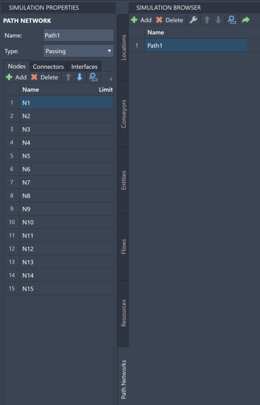
In the Simulation Properties panel, you can change the Path Networks' name and type. You can also make changes to your Nodes, Connectors, and Interfaces.
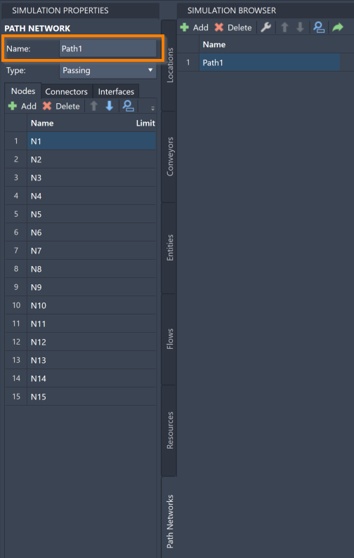
To change the name of a Path Network, select the Name value in the Simulation Properties panel.
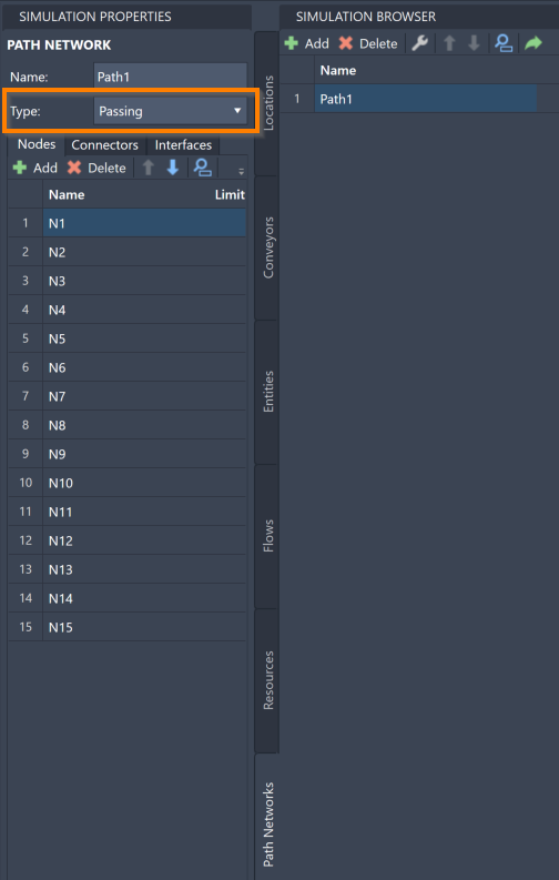
The Type menu allows you to change the Path Network configuration. There are two types of Path Networks:
- Passing - Used for open path movement where Entities and Resources are free to overtake one another.
- Non-Passing - Consists of single-file tracks or guide paths such as those used for AGVs where vehicles are not able to pass.
The Simulation Properties panel also allows you to view and edit the individual Nodes, Connectors, and Interfaces within a Path Network.
Nodes
To access Path Networks Nodes, select the Simulation Properties' Nodes tab.
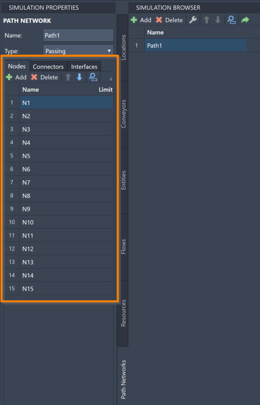
To add new Nodes to your Path Network, select Add on the Nodes toolbar. The Draw, Branch, Connector, and Interface menus open in the command box, which you may then use to edit your Path Network on the layout.
To delete a Node, select the Node in the Simulation Properties panel and select Delete on the Nodes toolbar.
To reorder your Nodes within the Simulation Properties panel, select a Node and use the blue arrows ![]() to move the Node.
to move the Node.
To locate a specific Node within your model, select on the search icon ![]() to open the search panel.
With the search panel open, type a Node' using it's name.
to open the search panel.
With the search panel open, type a Node' using it's name.
To navigate to a specific Node within your AutoCAD® drawing, select a Node within the Simulation Properties panel and select the navigate to icon  .
.
To change the name of a Node, double-click the Node's Name and revise.
Connectors
To access the Connectors in a Path Networks, select the Simulation Properties' Connectors tab.
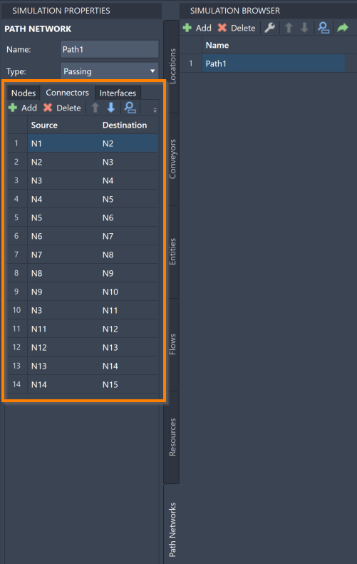
To add new Connectors to your Path Network, select Add on the Connectors toolbar. This opens the Draw, Branch, Connector, and Interface menus in the command box, which you may then use to edit your Path Network on the layout.
To delete a Connector, select the Connector in the Simulation Properties panel and select Delete on the Connectors toolbar.
To reorder your Connectors within the Simulation Properties panel, select a Connector and use the blue arrows ![]() to move the Connector.
to move the Connector.
To locate a specific Connector within your model, select the search icon ![]() to open the search panel.
With the search panel open, type any Connector information defined for it.
to open the search panel.
With the search panel open, type any Connector information defined for it.
To navigate to a specific Connector within your AutoCAD® drawing, select a Connector within the Simulation Properties panel and select the navigate to icon  .
.
To change a Connector's source or destination, select a Node under the Source or Destination columns to open a menu of your created Nodes. Changing this setting moves the Connector to reflect its new source or destination Nodes.
The Direction column allows you to change the Connector's direction settings. There are two types of directions:
- One Way - Connectors only allow Resources and Entities to move along them in one direction, specifically from the source Node and towards the destination Node.
- Two Way - Connectors allow Resources and Entities to move along them in either direction.
Select the Direction value to open a menu to select one of these two options.
Interfaces
To access the Interfaces in a Path Networks, select the Simulation Properties' Interfaces tab.
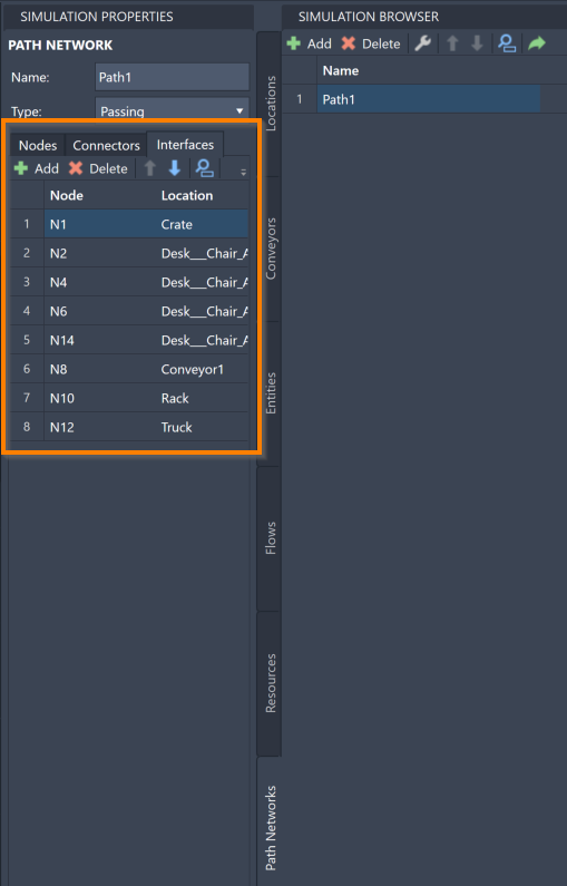
To add new Interfaces to your Path Network, select Add on the Interfaces toolbar. This opens the Draw, Branch, Connector, and Interface menus in the command box, which you may then use to edit your Path Network on the layout.
To delete an Interface, select the Interface in the Simulation Properties panel and select Delete on the Interfaces toolbar.
To reorder your Interfaces within the Simulation Properties panel, select an Interface and use the blue arrows ![]() to move the Interface.
to move the Interface.
To locate a specific Interface within your model, select the search icon ![]() to open the search panel.
With the search panel open, type any Interface information defined for it.
to open the search panel.
With the search panel open, type any Interface information defined for it.
To navigate to a specific Interface within your AutoCAD® drawing, select an Interface within the Simulation Properties panel and select the navigate to icon  .
.
To change the Node that is participating in the Interface, select a Node in the Node column to open a menu of your created Nodes. Selecting a different Node moves the Interface line to reflect your choice.
To change the Location that is participating in the Interface, select a Location in the Location column to open a menu of your created Locations. Selecting a different Location moves the Interface line to reflect your choice.