Simulation Browser: Path Networks
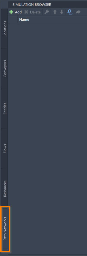
The Simulation Browser's Path Networks tab allows you to add, delete, and reorder model Path Networks.
Path Networks allow Resources to move between Locations. When a Resource is assigned to a Path Network, the Resource follows the Path Network as it navigates through the system. Entities moving by themselves may also use Path Networks, but usually use the Flow they are assigned to instead.
Examples of Path Networks are interconnected hallways in an office building, roads or tracks that vehicles move on, or aisles between shelves in a warehouse.
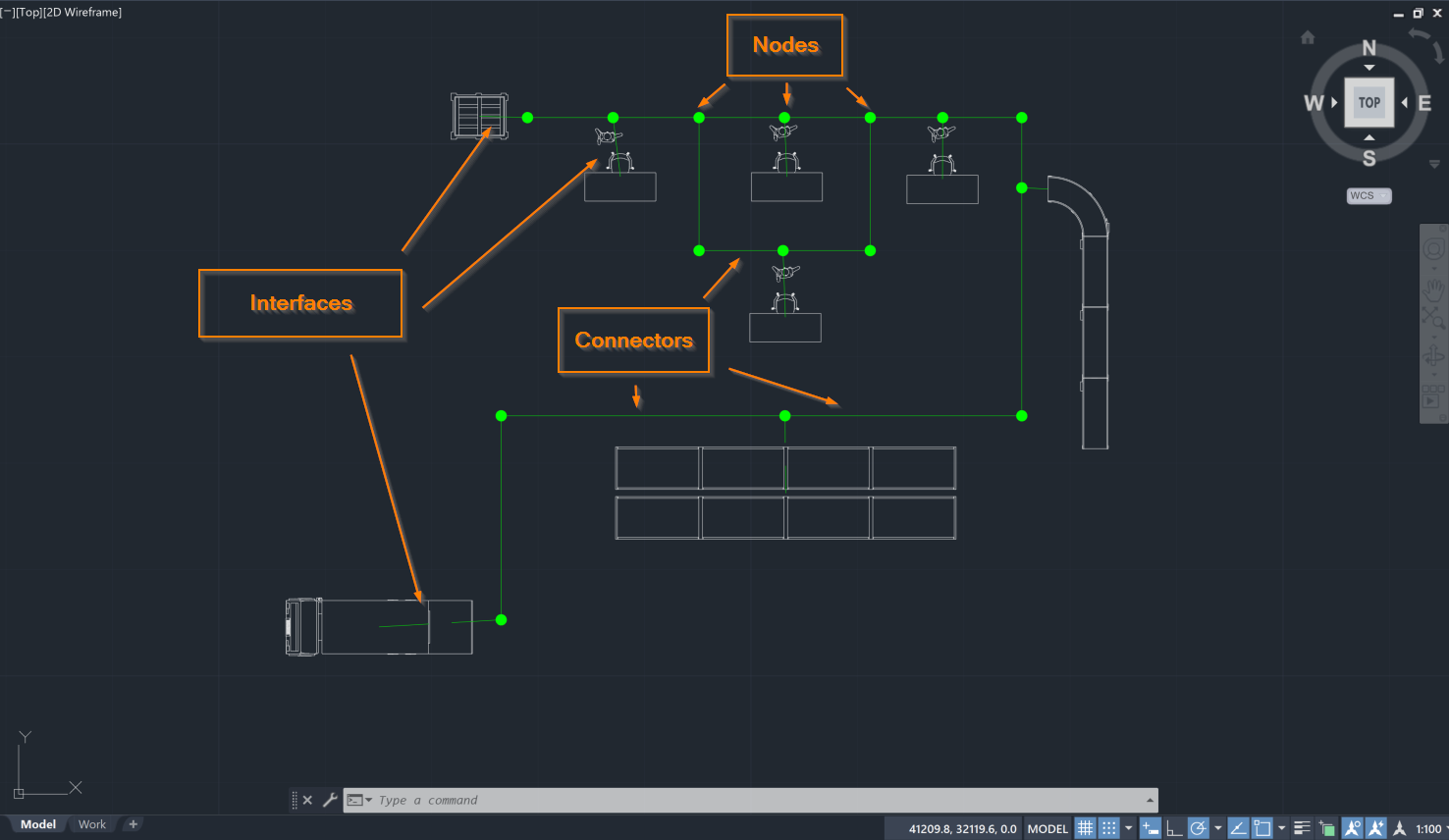
Path Networks are composed of Connectors, Nodes, and Interfaces.

Connectors are the path segments that combine to create the completed Path Network.
Nodes mark the beginning and end of each connector. Nodes can be thought of as the joints that allow a Path Network to bend and wind in order to reach all the necessary Locations throughout your model.
Interfaces are a special type of Node that define the relationship between a Node and a Location. Interfaces are used when an Entity or Resource moving on a Path Network needs to travel to and interact with a Location, such as a worker (Resource) using a machine (Location).
Note that only one Node may interface with a particular Location from the same Path Network, but one Node may interface with multiple Locations.
Adding Path Networks
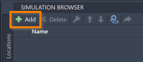
To add Path Networks to your model, go to the Simulation Browser's Path Networks tab and select Add.


This prompts the command box to open the following message:

Enter the name of your Path Network into the command box and select the keyboard Enter. This prompts the command box to open the following message:

You may now begin building your Path Network. Youautomatically start using the Draw feature, which allows you to select the layout to place Nodes. As you place additional Nodes, Connectors appear between them. To return to the Draw feature at any time, select the command box Draw.
To create additional Connectors, select the command box Connector. Select two or more Nodes to add Connectors to. Once you have chosen the desired Nodes, select the keyboard Enter to create the Connectors.
To create a branching path out of your main Path Network, select the command box Branch. Select a Node from your main Path Network for your branching path to stem from. After selecting a starting Node, you can add more Nodes and Connectors in the same manner while using the Draw feature. To connect your Branch back to your main Path Network, select a Node that is a part of your main Path Network and a Connector is added between the end of the Branch and your main Path Network.
To create an Interface, select the command box Interface. Select the Nodes and Locations to interface with one another. Note that Nodes that interface with Locations should be placed near the Locations, but not on top of them. This placement keeps the graphics from overlapping in an awkward way during the simulation. Once you have selected the desired Nodes and Locations, select the keyboard Enter to create the Interface.
Once you have finished adding all of your desired Nodes, Connectors, Branches and Interfaces, select the keyboard Enter. If you instead need to exit out of the adding process during any of the previous steps, select the keyboard Escape.
Path Network Tools
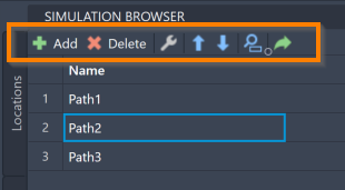
Once added to the model, you can use the Simulation Browser to delete, modify, reorder, search for, or navigate to your Path Networks within the model. These features are accessible through the Simulation Browser toolbar.

To delete a Path Network, select the Path Network name in the Simulation Browser and select the keyboard Delete. You may also right-click the Path Network and select Delete.
To modify your Path Network, select the Path Network name in the Simulation Browser andselect the modify icon ![]() .
Repeat the selection and make any needed changes.
You can also right-click on the intended Path Network and select Modify Path Network.
.
Repeat the selection and make any needed changes.
You can also right-click on the intended Path Network and select Modify Path Network.
To reorder your Path Networks within the Simulation Browser, select a Path Network name and use the blue arrows ![]() to move the Path Network.
to move the Path Network.
To locate a specific Path Network within your model, select the search icon ![]() . The Full Text Search feature opens.
Type the Path Network name in the search panel. As you type, the list filters to show only Path Network names matching your input.
. The Full Text Search feature opens.
Type the Path Network name in the search panel. As you type, the list filters to show only Path Network names matching your input.
To navigate to a specific Path Network within your AutoCAD® drawing, select a Path Network name in the Simulation Browser and select the navigate to icon  .
.
For more ways to edit and interact with your Path Networks, see Simulation Properties.