Simulation Browser: Flows
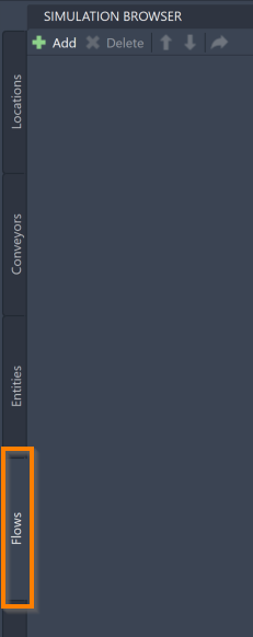
The Simulation Browser's Flows tab allows you to add, delete, and reorder model Flows.
Within a ProModel simulation, Flows define how Entities move through the model. Flows are responsible for determining where Entities go in the model, how they get there, and what happens to them at each Location. Either all Entities in the model can follow the same Flow, or each Entity can have its own Flow.
Adding Flows
To add a Flow to your model, go to the Simulation Browser's Flows tab and select Add.

You may also select the Add Process Flow icon on the ProModel ribbon.
![]()
If you hover over the Add Process Flow icon, you can see a tool description, as well as the command PMFlow.
Typing this into the command box is another way to add Flows.
This prompts the command box to open the following message:

Enter the Flow name into the command box and select the keyboard Enter. This prompts the command box to open the following message:

Enter the Entity name to follow this Flow and select the keyboard Enter. If the desired Entity has not been created, you may also enter the name of a new Entity to create and add it to the Entities tab when you select the keyboard Enter. You may also type ALL into the command box or select the ALL in the command box to make all created Entities follow this Flow.
For more information on Entities and how to use the Simulation Browser's Entities tab, see Simulation Browser > Entities.
Once you have selected an Entity to follow your Flow, you may now start defining how your Flow moves throughout your model.
To build your Flow, select the Locations or Conveyors to visit in order, meaning that the first Location you select is the beginning of your Flow, and the last Location you select is the end. As you select assets, they are added, in order, to the Simulation Browser.

As you hover your mouse over Locations or Conveyors, notice how the asset is highlighted. For the best results as you build your Flow, wait until you see this highlight on an asset before selecting it to ensure that it is selected correctly.
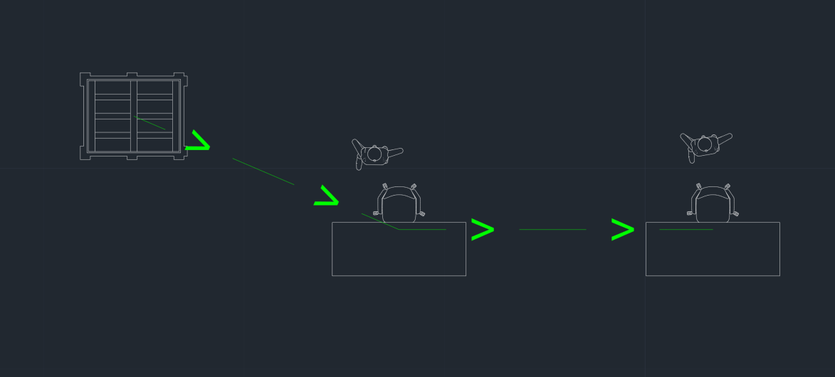
As you select assets to build your Flow, note that arrows visually display the Routes you are creating between Locations, which combine to create the full Flow.
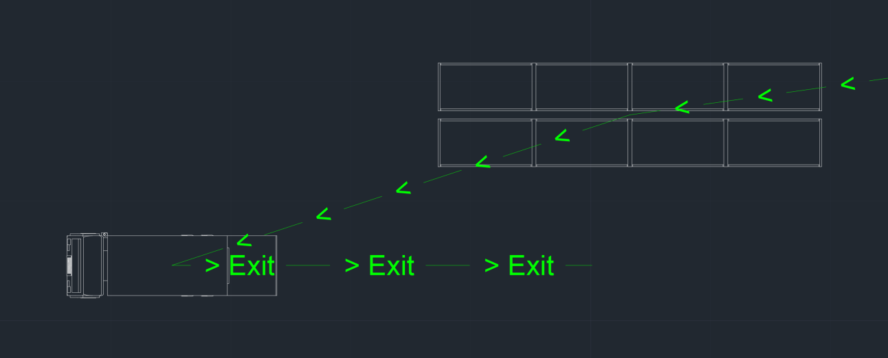
Once you have reached the final Location of your Flow, select the command box Exit to create an Entity exit Route. A line appears leading out from the final Location to represent your Entity leaving the model.

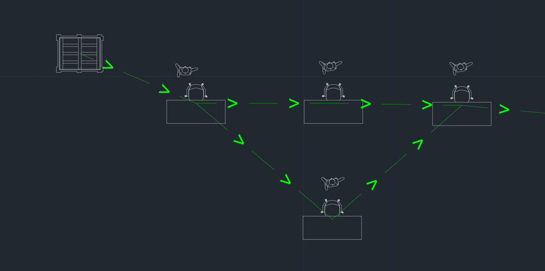
While building your Flow, you may also add branching paths that your Entity might take while traveling through the system. It is recommended that you first complete your main process Flow line, and then go back to add these branching paths. Once you are ready to add branches, select the command box Branch.

Next, select the Location in your main process Flow line where the branch stems from. Select the other Locations for this branch to travel to that deviates from the main process Flow line. Your branch must either rejoin with the main process Flow line so that it can also reach the exit Route, or end in a new exit Route at a seperate Location.
Once you have completed your Flow, select the keyboard Escape to complete the adding process.
Flow Tools
Once added to the model, use the Simulation Browser to delete, reorder, or navigate to your Flows within the model. These features are accessible through the Simulation Browser toolbar.
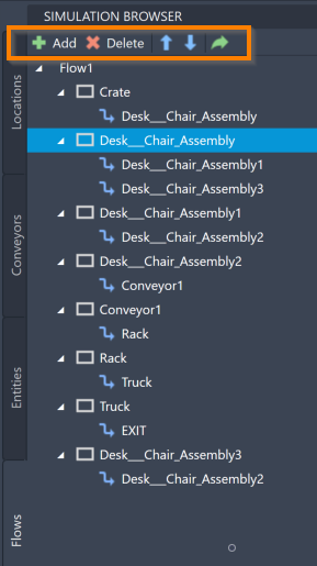
To delete a Flow, select the Flow in the Simulation Browser and select the keyboard Delete. You may also right-click the Flow and select Delete.
To navigate to a specific Location, Conveyor, or Route within your Flow on your AutoCAD® drawing, select the item within the Simulation Browser and select the navigate to icon  .
.
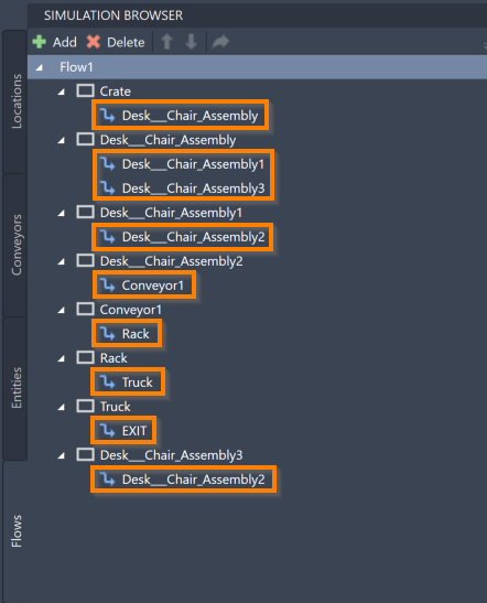
You can also use the Simulation Browser to modify the different pieces of your Flow. To delete any Routes between assets, right-click the Route within the Simulation Browser panel (denoted by a blue arrow to the left of its name) and select Delete.
To delete any Locations (including Conveyors) within your Flow, right-click the Location within the Simulation Browser panel (denoted by a white rectangle to the left of its name) and select Delete.
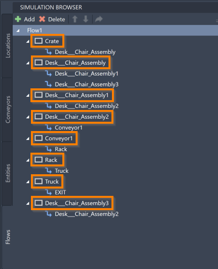
You may also use the Locations in the Simulation Browser to add new Routes to your Flow. Right-click a Location and select Add Route. This causes the following message to open by the command box:

Select the next Location by selecting the asset in the layout, which creates a new Route branching from the Location that you initially selected. You can also right-click a Location and select Add Exit Route to denote the Entity leaving the system from that Location.
Another way to add additional Routes to your Flow is to right-click your Flow and select Add Process. This allows you to use the layout and select assets to add to your Flow, much like the initial adding process.
To reorder the Locations within a Flow, select a Location and use the blue arrows ![]() to reorder its place within the Flow sequence.
to reorder its place within the Flow sequence.
For more ways to edit and interact with your Flows, see Simulation Properties.